
Impedance Analyzer
Link to repository
The motivation for this project came when building filters for the MPI system. I often needed to measure filter elements (LC Tanks, etc.) at very specific frequencies, for example to find a network’s resonance, and quality factor. The LCR meter that was available in lab has only discrete frequencies (100 Hz, 1kHz, 10kHz, etc.), and is therefore unsuitable for this application. Alternatively I could try to use a function generator and oscilloscope, but that is somewhat of a hassle to set up and analyze the results of. Vector network analyzers are large and/or don’t go down to such a low frequency.
I was also motivated to build it as an exercise. I want to become a better designer, and focus on precision/understanding parasitic elements.
Here are a bunch of useful links:
https://www.nutsvolts.com/magazine/article/a_low_cost_rf_impedance_analyzer
https://www.industrial-electronics.com/elektor_303_10.html
https://www.elektormagazine.com/labs/remake-lcr-meter
https://www.ti.com/tool/TIDA-060029
http://ijiet.com/wp-content/uploads/2017/01/18.pdf
http://web.mit.edu/6.101/www/reference/M3LCR_manual.pdf
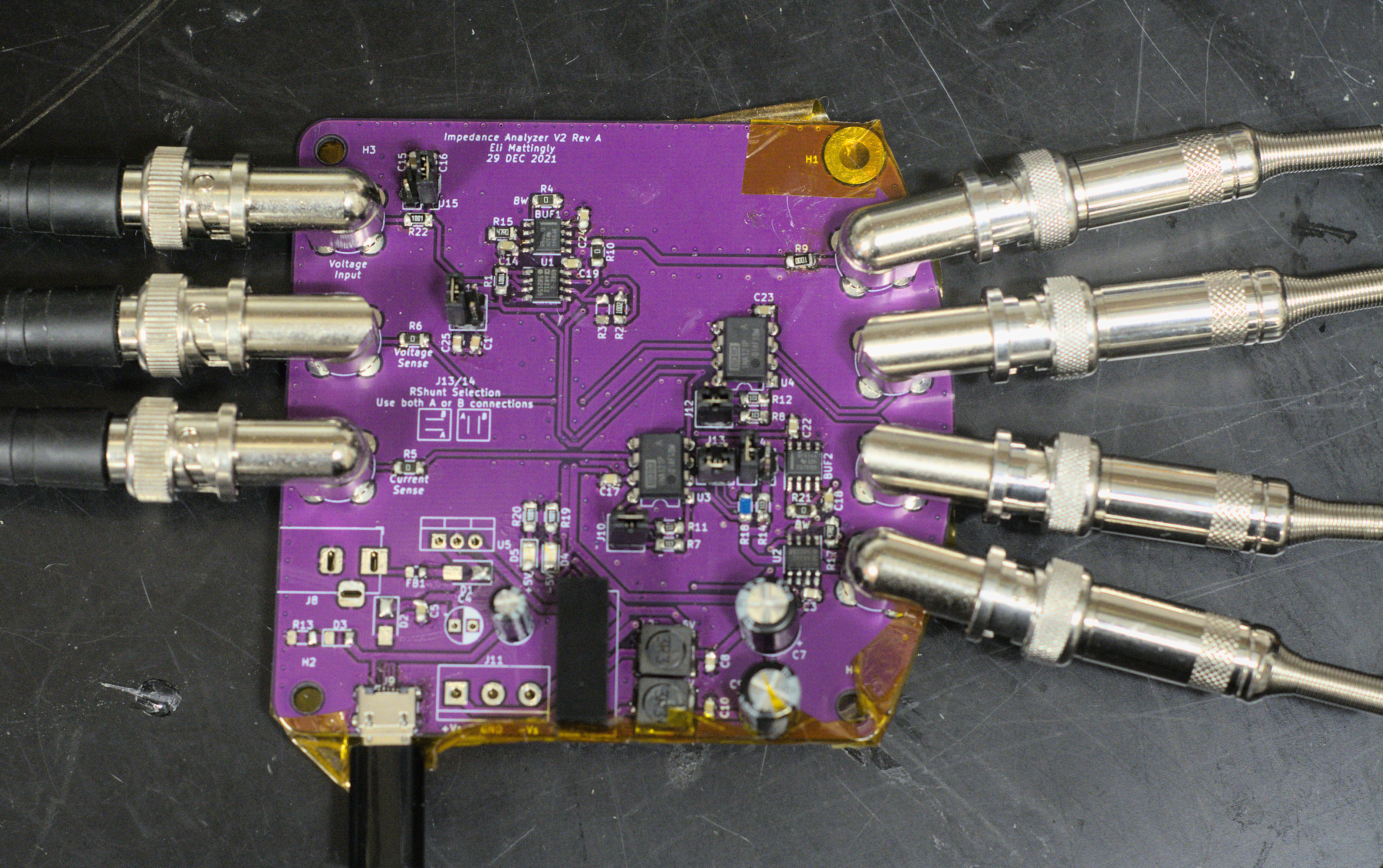
Circuit Described
The first version uses an I-V measurement approach with no solid buffer, but I quickly learned this method has many downsides. It is very functional and accurate, but has significant room to improve. The next revision uses the auto-balancing bridge, as is the standard in the field and improved buffers to allow for more current in low-impedance loads.