Microphone-Transducer_1
The actual microphone element
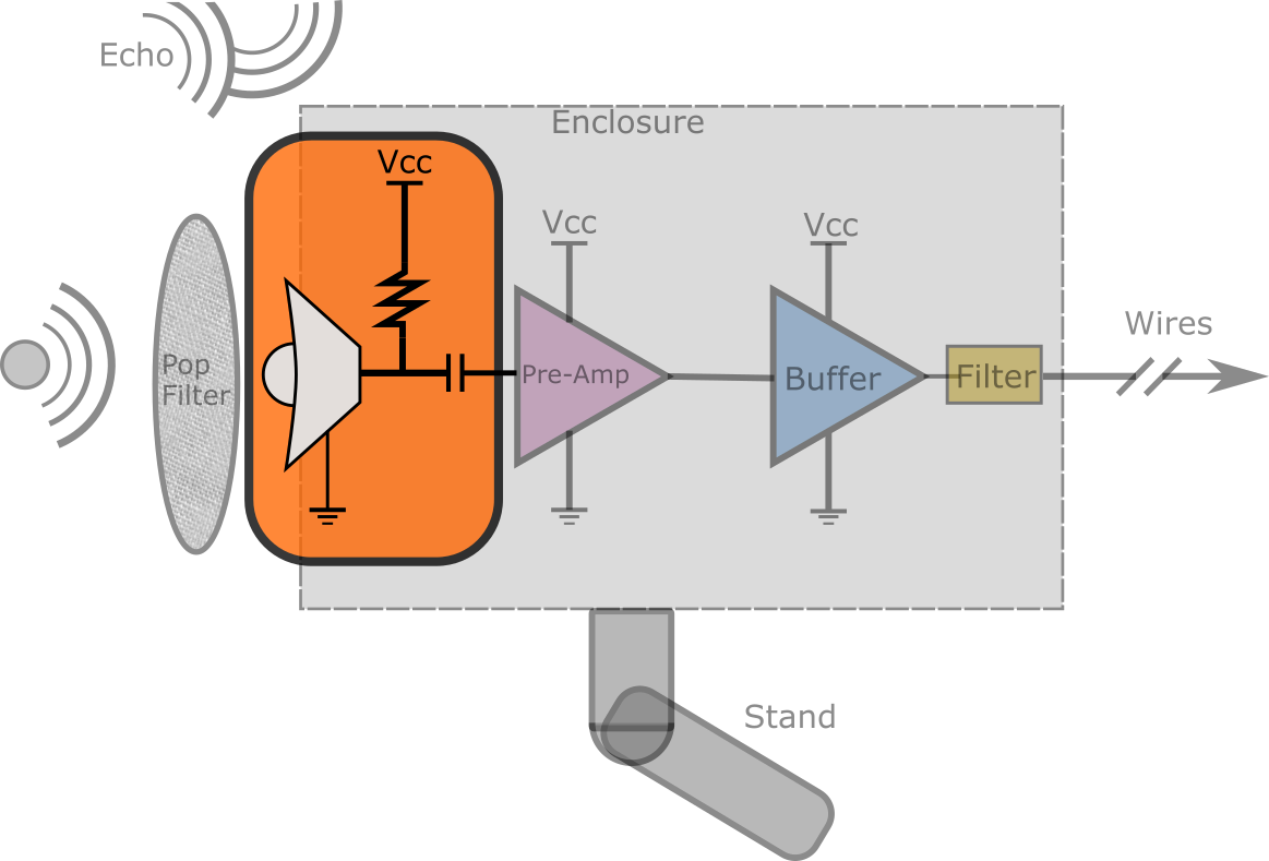
The microphone (a.k.a. transducer) element is without doubt the heart of this project so I’m going to tackle it first, and then inevitably realize half of what I say is either uninformed or plain wrong so I’ll update this as I go. Being so central to the project essentially the rest of the project is designed around this transducer element. So first lets just lay out the options of what kind of microphones there are:
- “Dynamic microphones” are essentially the reverse of normal speakers. It is a stationary cylindrical permanent magnet that with a coil around it. The coil moves with a diaphragm, so as there are incident (meaning oncoming) sound waves, the diaphragm moves which therefore induces voltage across the coil (Faraday’s law of induction). While I haven’t verified this myself experimentally, it seems to be generally suggested that these are a bit better for things like recording concerts or bands where a high dynamic range is important.
- “MEMS” microphones are Micro-ElectroMecanical System. These seem to be rapidly advancing and according to my reading show a lot of promise. I’m personally avoiding them to start, though. The reason being that the realm of MEMS transducers seems to be quite heterogeneous, and there is a lot of integrated circuitry built into many chips, which I personally don’t want. They are also a bit harder to work with because they are often very small and geared towards production which means you need to solder oven them on. And I don’t have a solder oven.
- Piezo-Microphones are similar to MEMS in a sense. I haven’t seen too much advice regarding them or many of them on Digikey. They work by compressing specific “piezo-electric” materials, that when deformed result in a voltage formed.
- Condenser Microphones are the gold standard for studio microphones, it seems. They are very high sensitivity, but also very expensive (at least $50). The bigger issue for me is that I really had trouble finding any of the raw condenser elements. They operate by having two parallel plates near each other with one being charged to on the order of 48V (with what is commonly called phantom power) and then with incident sound waves come in it makes the plates get a bit closer together. Now, if we recall the equation for a capacitor is C=Q/V where Q is charge (coulombs) and V is voltage. If we move the plates closer together, the capacitance changes and therefore the voltage across the plates changes. Well, that is my understanding. A point of confusion I had is whether or not with these “true” condenser microphones operate by maintaining a charge, and changing capacitance, or if they maintain a voltage across the plates and the capacitance changing means charge will flow (i.e. current) and that moving charge causes a voltage across a load. I am pretty sure it is the former (fixed charge), but time will tell. Though in either case this voltage is extremely small so it needs to be immediately amplified, and that is often done with a JFET (Junction Field-Effect Transistor).
- The last category that I will discuss here is the Electret condenser microphone. For now, I’ll avoid getting into the mechanisms of how they work ,and further, how the mechanism inform design, but in short they are similar to the “pure” condenser microphones except that instead of being polarized by “phantom power” it is permanently polarized by a charged insulator in between the capacitor plates. This results in microphones that are both cheap, simple, and robust and simultaneously they are quite high quality. Because they are accessible and fairly high quality I will use them at least to start.
Electret Microphone Mechanisms
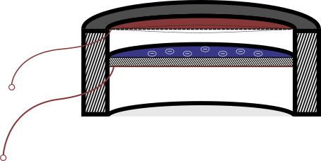
Into the weeds we go! I drew up a simple figure to depict the cross-section of a basic electret microphone (above), in that figure there are a few major components:
- The housing needs very little explanation. They are typically between 2mm and 10mm in diameter
- The top red semicircle represents the move-able diaphragm, as indicated by the dotted lines above and below the cut. This part is a very thin gold or nickel plated plastic and is exposed to oncoming sound waves. The plastic is often Mylar or other similar substrates. Not shown on this figure is a dust cover that will keep the very fragile diaphragm in tact. The metallized side is connected to a wire lead which connects to the pre-amplifier.
- The next part is the blue charged plate. This plate is both stationary and has appreciable thickness. It is this plate that gives the electret the name “electret”, because it is a permanently charged electrode. The etymology of the word, according to Wikipedia is a combination of “Electricity” and “Magnet”, so “Electr”+”et”. By permanent I mean many years before any degradation will occur due to the high resistivity of the material. Commonly this is Teflon. On the bottom side of the stationary electret is another gold or nickel film. I emphasize bottom because if it was on top there would be no charge between the conductors and it would no longer act as a charged capacitor.
- The two leads depicted in my figure are left open, but in most of the commercial capsules I have found, they are immediately attached to a JFET gate on one end and the ground reference on the other end. JFETs are a complicated topic, so that is for the next section.
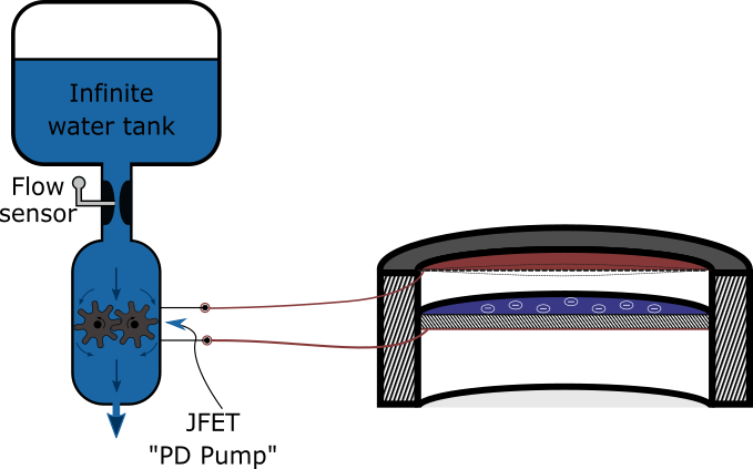
Brief aside on JFETs
This new figure above includes a gear pump (“PD Pump” = Positive displacement pump) as an analogy for the JFET, but if you are already familiar with these you can probably skip this, because it certainly isn’t a perfect comparison.
With that caveat out of the way, lets discuss JFETs conceptually and what we need to know for now. In the commonly applied arrangement, these JFET work through “trans-conductance”. This means that when an external voltage is applied the current changes proportionally. In my analogy, the external voltage is from the two microphone leads and this voltage will either slightly speed up or slow down the pump. By slowing the pump the amount of water flow will change in direct proportion and that is reflected by the flow sensor I drew, and the restriction would be the load resistor which is normally 2.2kOhms or so. The analogy is strained because without any charge, the JFET will naturally be mostly open so current/ water will flow. In practice the JFET found in electret microphones generally allows roughly 500microAmps to flow whenever the microphone is powered up.
Now let me reiterate the fact that this model isn’t perfect, but it mechanistically represents how most of the components go together. Having this mechanistic understanding will really help out when the questions arise such as can these microphones be attached in series or parallel, and what the implications are regarding noise.
My previous attempts at making an analogy
If you look in the folder where the images are stored for this page (../assets/images/Projects/Hobby/Mic) you’ll see there are a few versions behind the current. The biggest change is that I really didn’t like my valve analogy– in one sense it is a lot more accurate because inside a JFET it is a channel that gets narrower or wider which modulates the current, but on the other hand, if you did that with water the implications are a bit different. The PD pump really is a accurate current source analogy because it is for all intents and purposes (or “intensive purposes” depending on who you are) it is an infinite impedance. When a gear pump isn’t turning it functions as a closed valve. When a gear pump is running, and presuming it doesn’t break or run out of power, it will create any pressure needed to keep water flowing at its specified volume per turn.
Sources!
https://www.neumann.com/homestudio/en/what-is-a-condenser-microphone