Microphone-Transducer_2
Transducer post 2
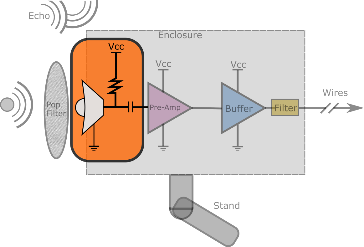
For this discussion I am assuming all electret microphone modules are manufactured with a JFET manufactured in place. With that assumption out of the way, lets begin remind ourselves why we picked an electret microphone. First, they are very economical, to the degree where the cost is dominated by shipping if you are getting a small amount (<$1 each), and second, they are fairly high sensitivity. But, while they have decent sensitivity, it is typically lower than a externally polarized condenser (a “pure” condenser).
My first thought to ameliorate this shortcoming of sensitivity was to use an array of them, but that isn’t a trivial question either. Do you put them in series or parallel? Will it help? Is it practical? If it works and is practical, how many will be needed?
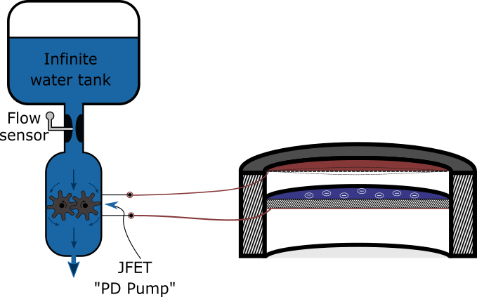
Back to the pump analogy! Lets say you have two of these pumps and you want more flow, but there is a limit on how much faster they can spin, what do you do? Well if they are in series, remember that the flow rate is wholly determined by the pumps rotation speed, so if one pump is spinning at 1000 RPM and the second pump is in series it *must* spin at the same rate so that it doesn’t fight the first pump. The amount of pressure generated by each pump is halved which poses some benefit, but it doesn’t get more flow. In the example below it shows what happens if they are ideal pumps at different rates, in the proximal pump is too fast, it will pressurize the region between the pumps and potentially burst a pipe (more likely it will stall). If the proximal (first) pump is slower, then the region between the pumps will become very low pressure and potentially cavitate.
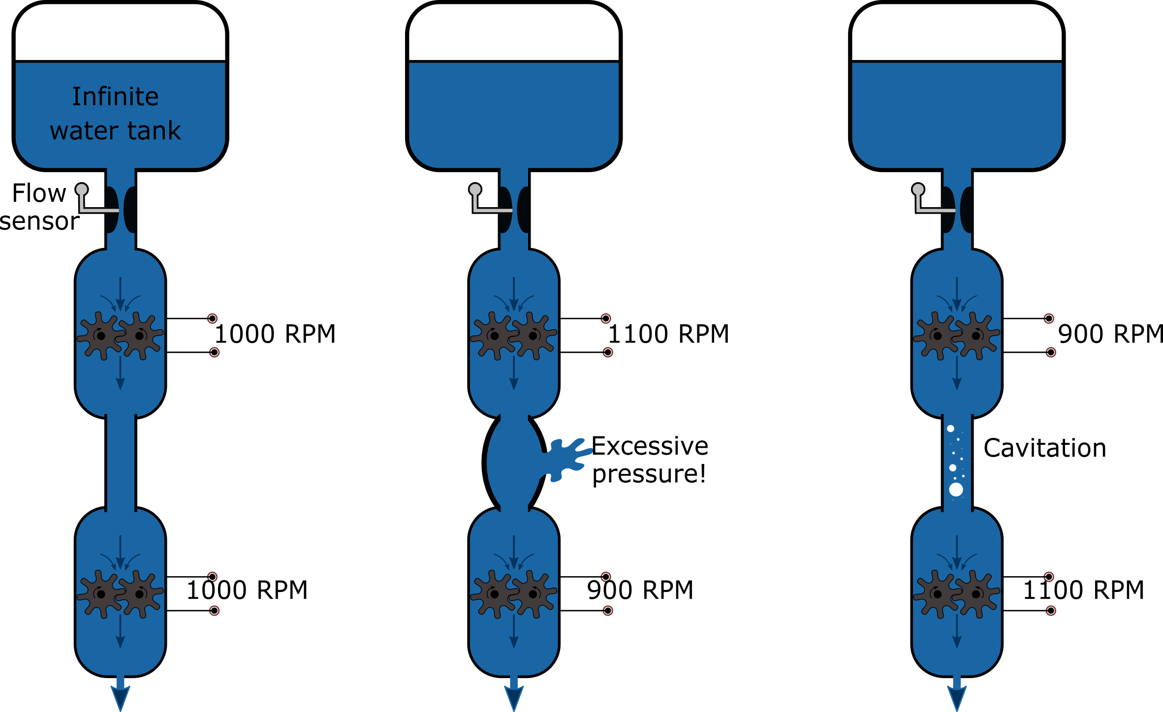
SIDE NOTE There is a glaring error with this figure with the three series pumps, if anybody even makes it this deep into these pages I’d be interested if somebody catches it. The answer is at the bottom.
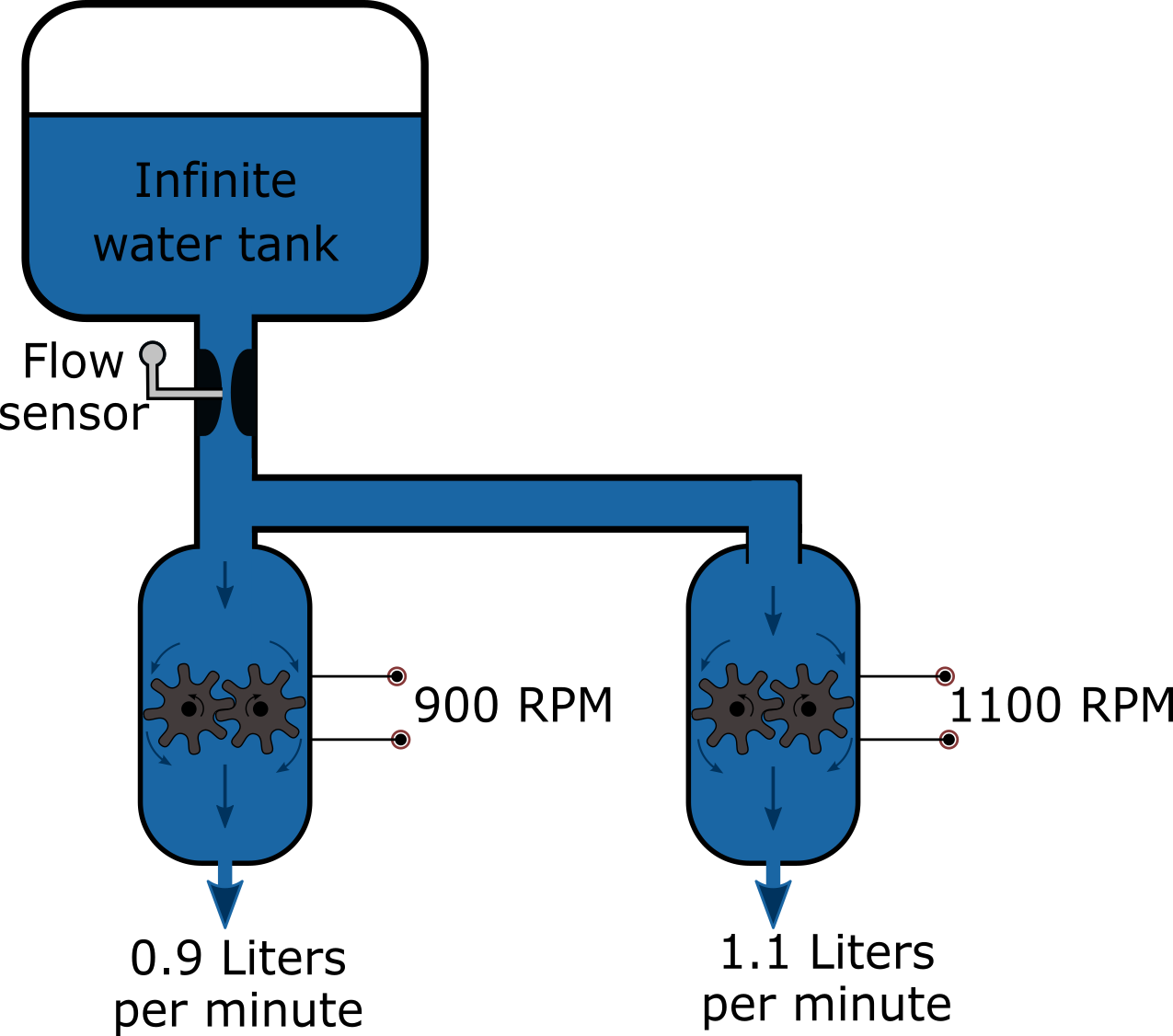
Now, let’s look at the case of parallel flows. If the pumps are both spinning at 1000 RPM and at that rate it pumps 1 liter per minute (arbitrary value), the net flow is 2 liters per minute. What is there is a slight mismatch, say because they were built to different specifications or there was noise in the control circuit? One pump now turns a bit too fast at 1100 RPM, and expels 1.1 liter per minute and the other is at 900 RPM and 0.9 LPM. The net flow is still 2 LPM, but no pipes burst or cavitated! Woohoo!
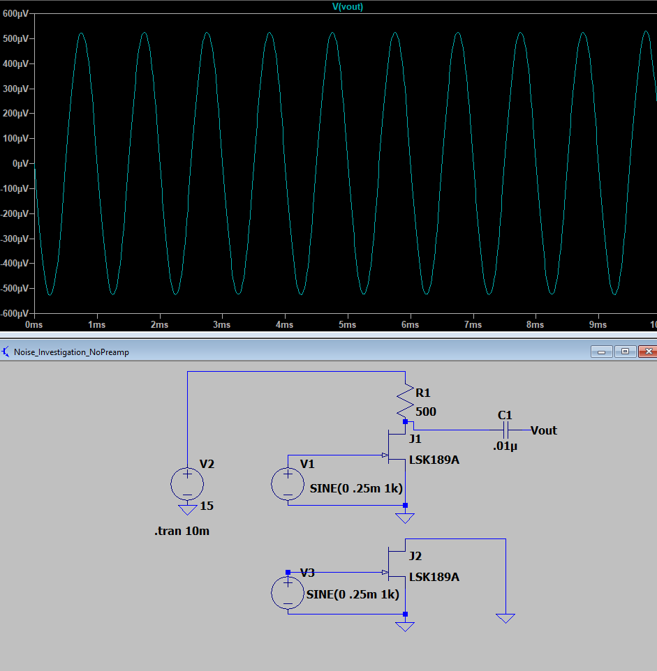
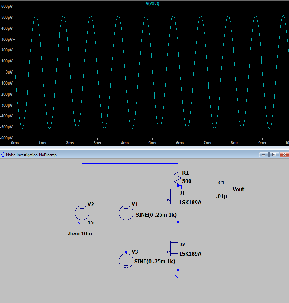
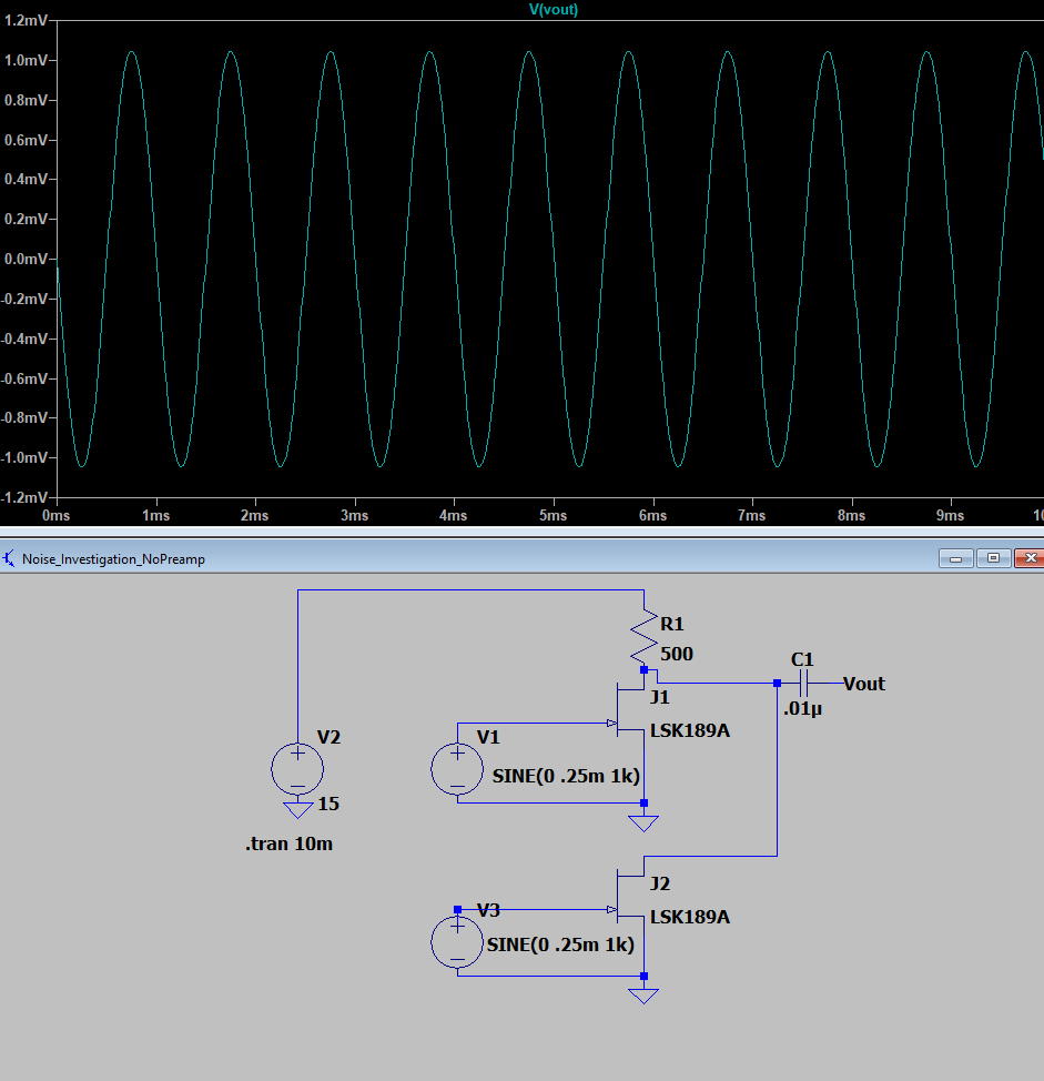
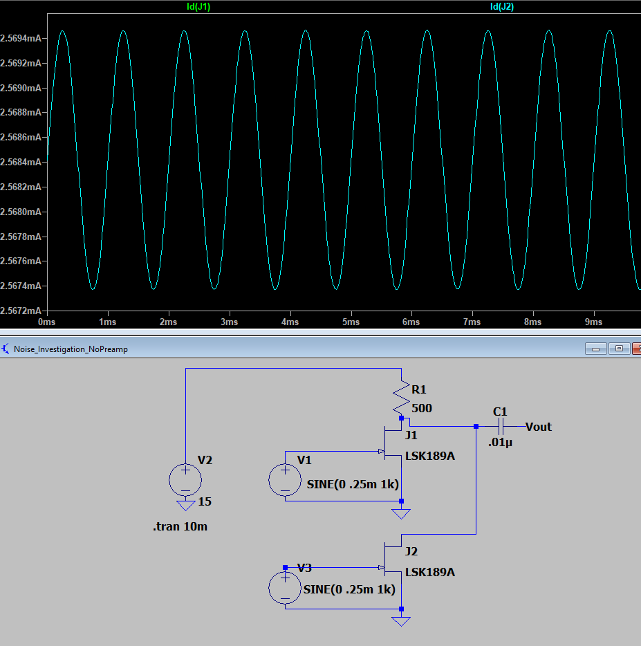
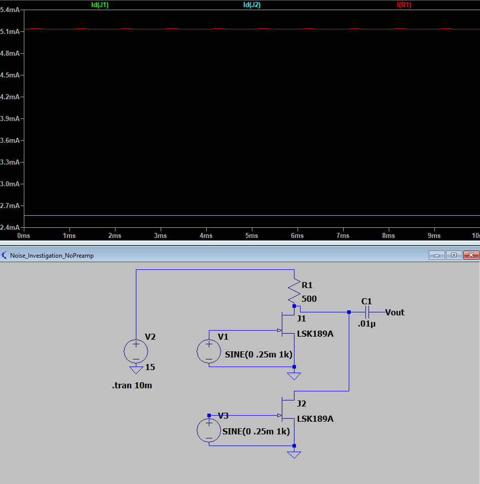
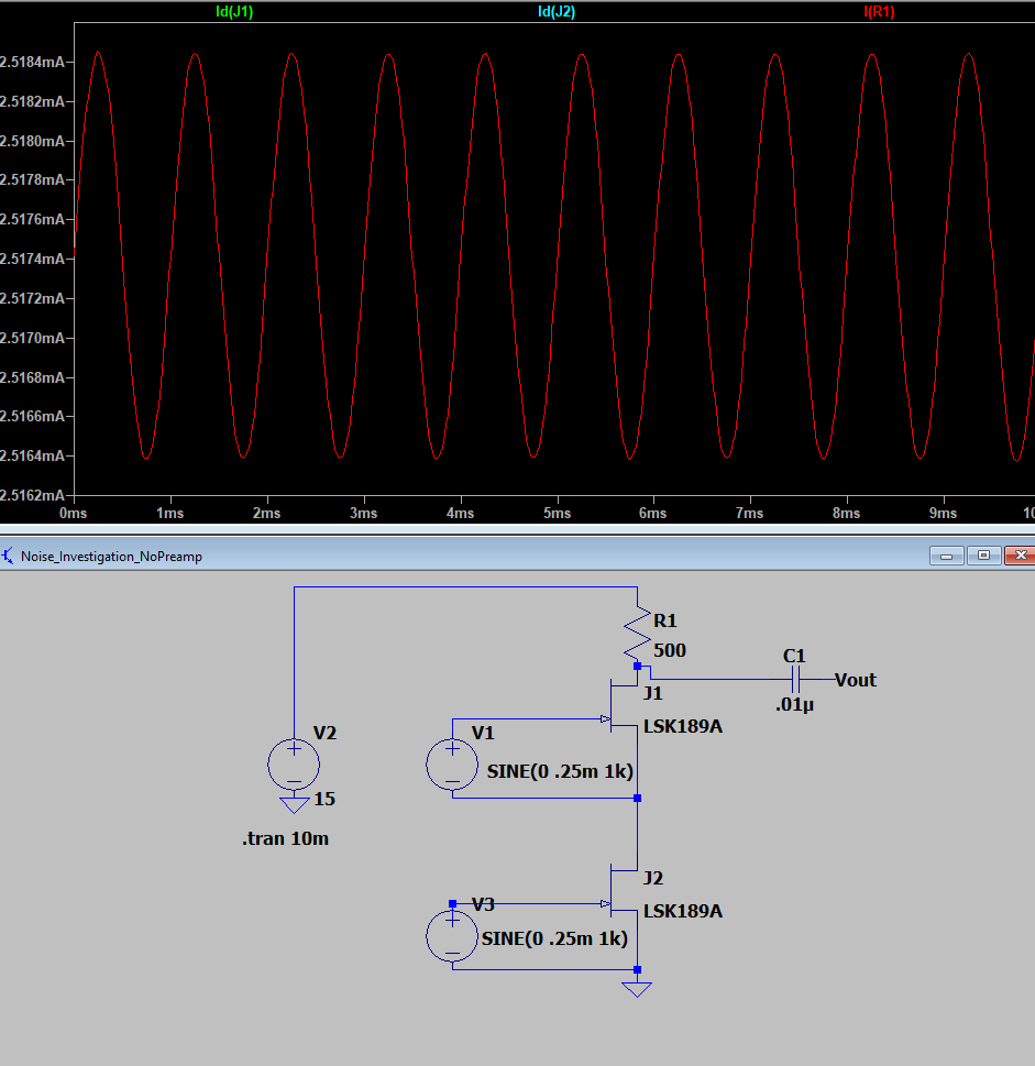
Now that we have this mechanistic understanding, does it translate to circuits? For now I don’t have the actual microphones so we need to live with LTSpice. In the series of screen shots below, the following can be observed: (i) when in series, the JFETS and resistor all carry the same current (are demanded by KCL). (ii) when in series, the Vout is the same as when there is only one JFET connected. (iii) When parallelized, current doubles through the resistor, and as a corollary the Vout doubled.
Looking at the case with only one JFET (the other is shunted to ground), Vout is ~1mV pk-pk/.
If we add a second in series the voltage out doesn’t substantially change.
In parallel the voltage doubles.
Below are the current scopes (they are over lapping in many cases).
I’m not going to take screen shots for the noise measurements in LTSPice, but the syntax is “.noise V(Vout) V1 oct 100 100 100k” which means look at the nosie at Vout from V1 with 100 points per octave from 100Hz to 100kHz.
When there is only one JFET: Noise is 4.56nV/sqrt(Hz) at the asymptote and signal was ~1mV so SNR for a 10kHz bandwidth, the SNR is 1mV / (4.56nV/sqrt(Hz)x sqrt(10kHz)) = ~2000
With series JFETS noise is 3.8nV/sqrt(Hz) This gives an SNR of ~2600
With JFETS in parallel, signal is now ~2mV pk-pk and noise is 5.75 nV/sqrt(Hz) This gives an SNR of ~3500.
This nearly exactly reflects the theoretical value of a sqrt(2), or a 1.4x improvement. The reason you would expect a sqrt(2) improvement is that the signal has doubled but a true (incoherent) noise will grow with the RMS of the amplitudes. So signal is 2x and noise is (sqrt(N^2+N^2) where N is the noise figure of one JFET.
The other subtlety of this is that the resistor value should, in practice, decrease in value so that the operating point stays the same throughout.
But alas, I’m getting tired. So, to summarize we can add these electret microphones in parallel, but the benefit quickly decays and quiescent current linearly rises which might have negative implications if it is battery powered.
The big error in the series pumps figure.
I corrected it in the other two pump figures, but if you are familiar with the way gear pumps work, they spin so the teeth pull water around the outside of the housing and the center interference is a tight enough fit so no water can get between the teeth in the middle. AvE on YouTube has a bunch of tear-downs of gear pumps I believe. Anyway, it’s sad I spent so long drawing these and didn’t notice that until I posted this page. But oh well, I like keeping these mistakes up.