Microphone-Preamp_1
Pre-amplifier 1
An initial caveat I’m trained in mechanical engineering, so this shouldn’t be considered a guide for component selection or amplifier design. One of my main goals working on this microphone is as an excuse to help me study analog circuit design. Nonetheless, I like to think I am fairly informed and that this will help people with similar projects, but for an authoritative resource it is better to read books such as “The Art of Electronics”.
Let’s recap, so far it is clear that the typical electret microphone capsule is a good option for this project, and by added them in parallel we can (hopefully) get better SNR, if the microphone itself is the limiting factor for noise. But at this point our signal is a current not a voltage, and further is it on on the order of micro-amps (0.000001 Amperes). To get something useful from that signal two things need to happen, it needs to be translated into a voltage, and amplified so that it is ~1 volt. The former is pretty straightforward, the latter not so much.
To translate a current into a measurable voltage, the simplest solution is to use a resistor in series, and measure the voltage drop. By adding that series resistor what we are actually doing is creating a “common source” amplifier, but more on those specifics later. For now let’s just assume we have an ideal current source 1 micro-amp(uA) fluctuating with the audio on top of the roughly 100 micro-amps(uA). Maybe it is 5 uA fluctuating on 500uA, but that’s not the point. By applying Ohms law, the voltage will be proportional to the series resistor. So how should we pick that resistor value? I think there are two main options, one is to shoot for a DC voltage drop that is half the value of the supply voltage. The other option is to make it so that the minimum voltage (AC and DC component) is slightly above the minimum allowable for the JFET to be in its linear (“saturation”) regime. The second case would, in theory, give more signal because resistor is greater and therefore the AC component is multiplied by a greater number. But in practice I think there is some balance between the two, where the exact value is context-driven. In my case, I’ll be using 5V power, and I don’t want to get much below 2V, because I think I’ll be encroaching on non-linear regions of the integrated JFET of the microphone capsule (and the manufacturer doesn’t specify it).
Here’s what that looks like:
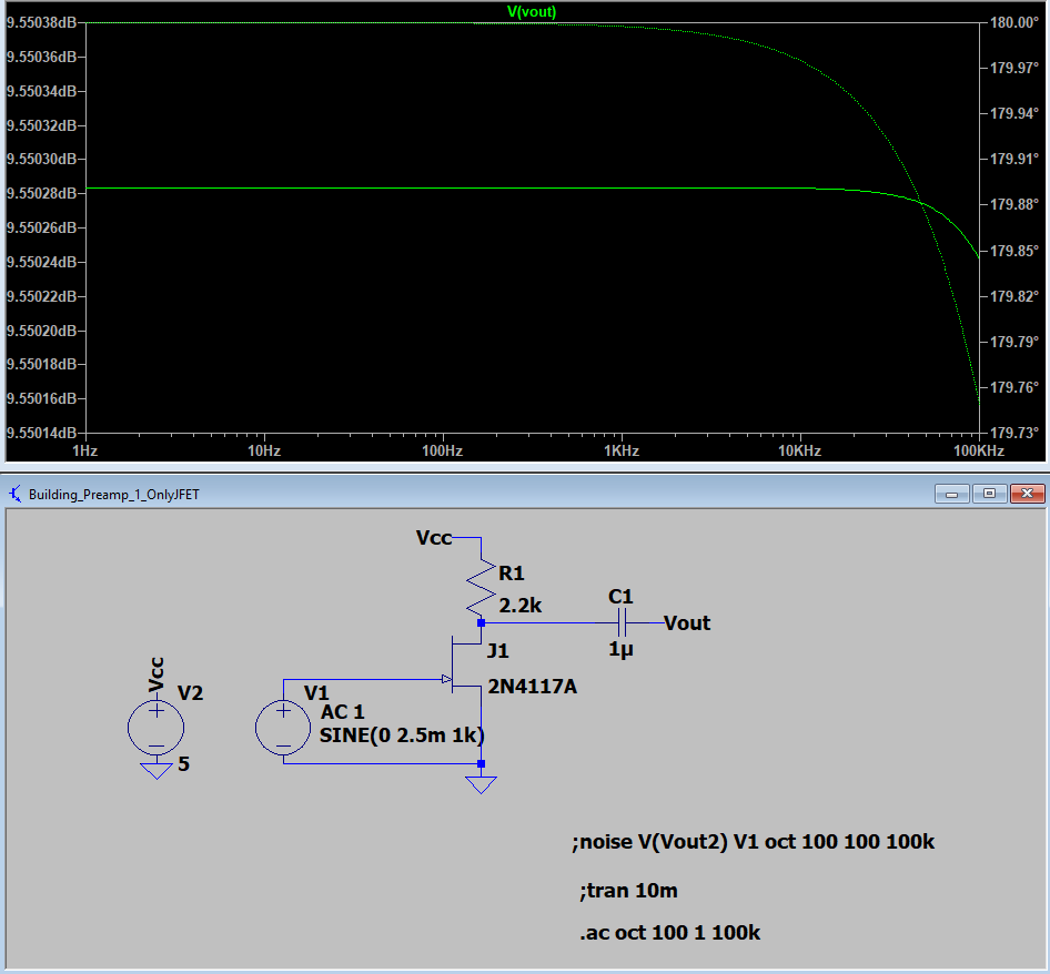
In that figure, the voltage source V1 represents the voltage across the electret microphone capacitor, which goes directly to the gate of a JFET, which would be manufactured as one unit. The JFET I chose was semi-arbitrary. The value of R1 should be tuned to the microphone as discussed above. Here, 2.2k Ohms seems to work well. The capacitor C1 “AC-couples” the circuit, but that will come into play next. The other thing worth noting is 9dB on 2.5mV is pretty meager, it is only a gain of 3. To improve that there are a few approaches (as always), and I’ll discuss the other approaches in time. But the easiest is to throw an OpAmp right after it. One example of this is demonstrated in US Patent No. 5,577,129. In that patent the opamp is configured as “inverting”, but another approach is to use a “non-inverting”, and an example of each is below. In this case, phase of the signal is unimportant and they have roughly the same size components, so I think they are fairly equal in terms of performance.
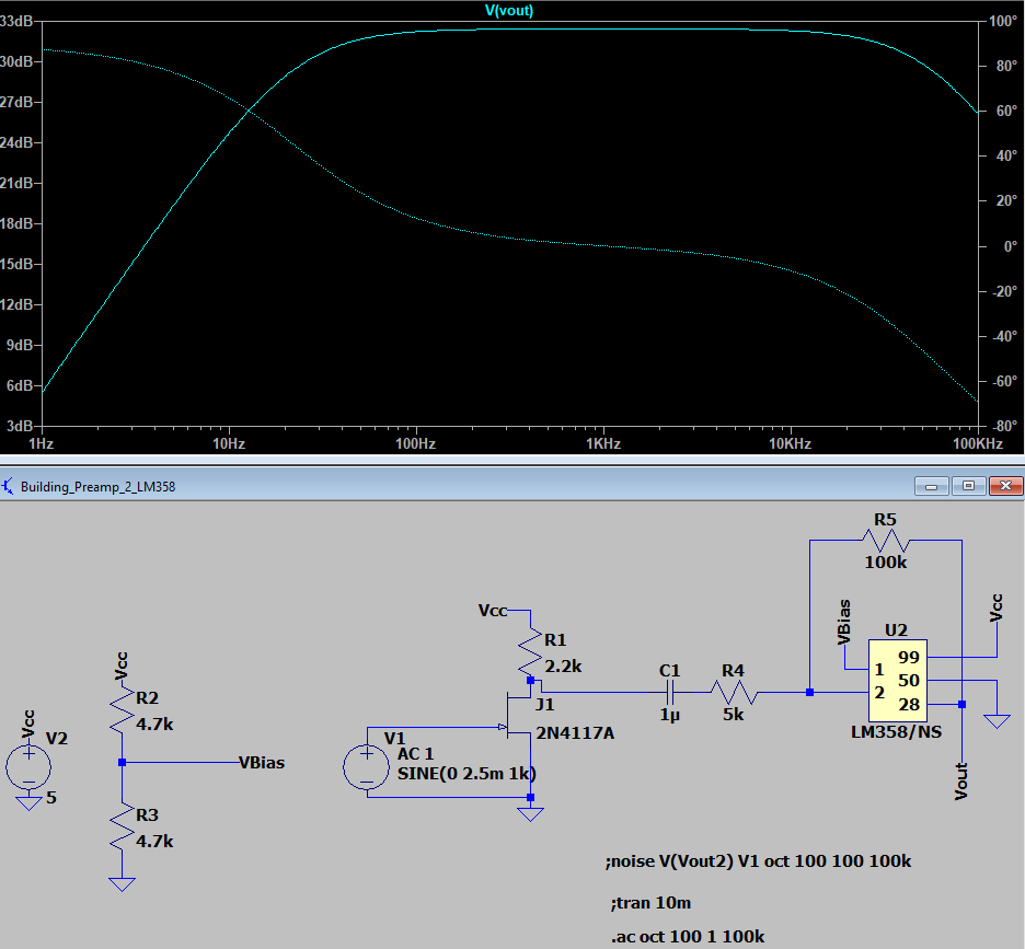
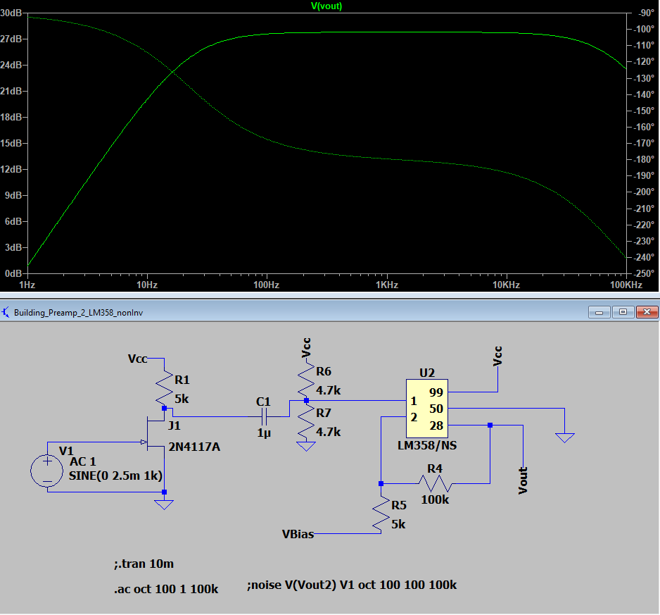
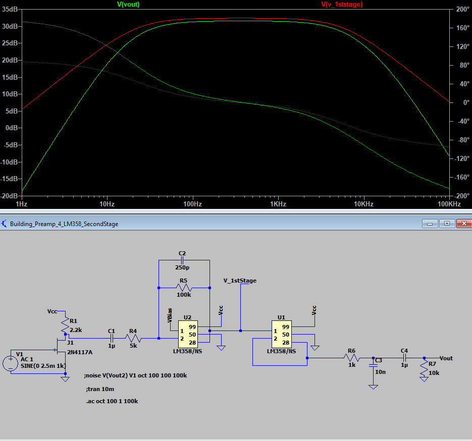
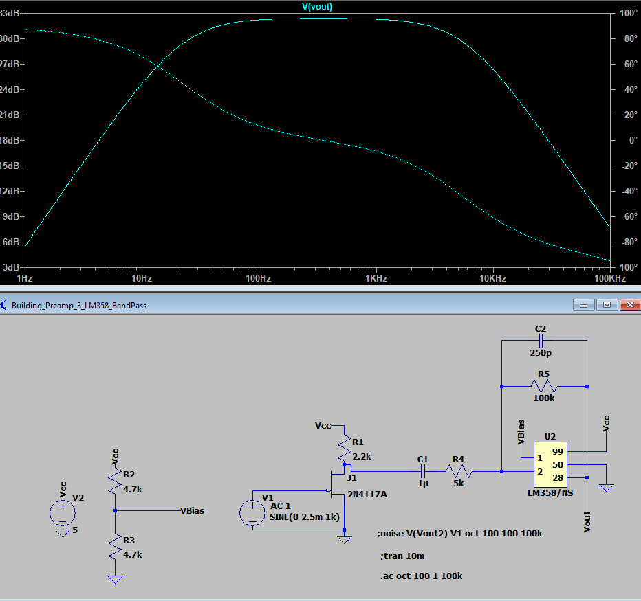
I’ll be sticking with the inverting configuration because it is what I am a bit more used to, and it seems to be the more common approach. In the figure, pin 1 is the non-inverting terminal, pin 2 is the inverting terminal, 99 is positive supply, 50 is negative supply (GND in my case), and 28 is the output. From this figure it is also clear the bandwidth is quite large at about 100kHz. We don’t like this because it allows more of the high frequency noise to pass through the amplifier (and be amplified). Luckily, within this opamp configuration we only need to add a single capacitor to accomplish this. By putting a capacitor in parallel with R5 we essentially “short-circuit” it at high frequencies, and because the gain is reliant on R5 being large, we diminish the amplification at high frequencies. The frequency which is called the “cutoff frequency” is calculated by 1/(2piC2*R5) in this case. You’ll also notice the low frequencies are attenuated as well, and that is because C1 and R4 act as a “high pass”.
As it stands in the figure above, you’ll have a perfectly reasonable amplified signal which can go into the computer, BUT I think there is still room too improve. First, partially because of paranoia, I will put a buffer stage amplifier. This “protects” the previous stage from changes in the surrounding circuitry, and to my understanding is generally good practice. For me this practice seems to help. There are two amplifiers in the LM358 anyway, so it is essentially free to use. After the buffer I I want to add another pair of filters. The first one, R6 and C3 act to filter out the high frequencies even further than before. The cutoff frequency for the system is rather low for audio, but I think this microphone will be for voice-over recording, and almost no information is above 5kHz anyway. The second filter removes any low frequency signal which may have made it through before as well as removing the DC bias which was previously necessary to stay within the operating range of the OpAmps.